IEC 60601-1-8: 12 steps back to conformity
The IEC 60601-1-8 is a collateral standard to the IEC 60601-1, the standard containing the general specifications. The IEC 60601-1-8 sets out requirements for alarm systems and their documentation and testing. It gives manufacturers specific instructions on the specification and for designing your medical devices.
Manufacturers, however, need to be familiar with the large number of terms that the standard defines. They should also know and implement the expanded requirements set out in amendment 2 to achieve conformity of their products and avoid problems with audits and authorizations. This can be achieved in 12 steps.
1. IEC 60601-1-8: what it’s about
a) Alarms – a matter of life and death
Alarms are often the last chance to prevent damage to patients, users, and third parties.
- The ventilator emits an alarm for the nursing staff if the breathing tube has been inserted incorrectly.
- The dialysis machine provides a warning if there is a risk of the patient bleeding to death.
- The infusion pump provides a warning that the medication reservoir is nearly empty.
- The monitoring system on the intensive care ward alerts the nursing staff in their monitoring room if a patient experiences a cardiac arrest.
Alarms indicate a potential or actual dangerous situation (patient, operator, device) for which attention or a response from the operator is required. Since the extent of the damage generally increases over time, alarms provide the necessary leeway to avoid serious damage.
Alarms are therefore actions to reduce the risk (in this case the probability). The effectiveness of the alarms must therefore be proven in the usability assessment (see section 4 e)).
It is therefore necessary to minimize the risks which occur if these alarms
- are not triggered,
- are not noticed (e.g. not heard or seen),
- are incorrectly understood,
- are ignored, or
- even lead to other risks such as usage errors.
The IEC 60601-1-8 aims to minimize precisely these risks and to contribute to making alarms a risk control measure that is as effective as possible.
b) Scope of the IEC 60601-1-8
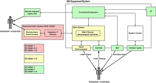
The IEC 60601-1-8 is a collateral standard to the IEC 60601-1. It therefore also targets medical electrical (ME) devices and systems made of ME equipment.
This collateral standard specifies requirements for ALARM SYSTEMS and ALARM SIGNALS in ME EQUIPMENT and ME SYSTEMS.
IEC 60601-1-8
Definition: Medical electrical system
“combination, as specified by its MANUFACTURER, of items of equipment, at least one of which is MEE to be inter-connected by FUNCTIONAL CONNECTION or by use of a MULTIPLE SOCKET-OUTLET”
IEC 60601-1-8
Examples of ME equipment include the medical devices mentioned above: ventilators, dialysis machines, infusion pumps, monitoring systems, and distributed alarm systems. These can be classified into:
- Therapeutic (vital) systems
- Systems to monitor the patient’s health condition
- Distributed alarm systems
The standard therefore relates to those parts of ME equipment (ALARM SYSTEMS) which detect alarm statuses and generate alarm signals, in other words all statuses which require immediate action by the operator.
The standard included non-ME equipment in distributed alarm systems, e.g. standalone software in a patient monitoring center or dismissed alarm displays. It does not, however, set out any technical requirements of the functioning of alarm systems of this type.
Manufacturers of standalone software that runs on generally available devices (e.g. smartphones, pagers) and forward on alarm statuses or display them remotely should also take the standard into account.
Further information
The article on IEC 60601-1 (german) is a quick introduction to the world of ME equipment.
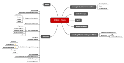
c) Overview of the standard requirements
The IEC 60601-1-8 sets out the requirements for alarms:
- Handling the urgency of alarms (priority)
- How alarms are signaled (visually, acoustically)
- Alarm behavior for alarm statuses (delay, suppression etc.)
- Labeling and accompanying documents
- Testing and validating alarm systems
The standard does not set out:
- The need for an alarm system (arises from the risk analysis or the individual standards)
- Circumstances that trigger an ALARM STATUS
- Allocation of alarms to priorities (sometimes this occurs in the individual standards)
- The technology for generating an alarm (e.g. piezo or loudspeaker)
The standard helps with the definition of terms as presented by Chapter 2 of this article.
d) Interfaces with other standards
Manufacturers and operators need to take into account other standards in the case of distributed alarm systems in particular. The following figure provides an overview.
2. Definitions: penetrating the jungle of terms
The standard defines a large number of terms which are difficult for laypeople to differentiate, but they don’t need to be understood to make a decision about when which requirement of the standard needs to be complied with.
Tip
You can check whether or not you know and have understood all of the terms if you cover the right-hand column of the table in Chapter 2 d) and find the matching terms yourself.
a) Alarms, alarm systems, alarm signals, alarm conditions and more
The IEC 60601-1-8 does not define the term alarm. It makes a distinction between alarm systems and alarm signals. It also differentiates between several types of alarm conditions.
An alarm system is defined as follows:
Definition: ALARM SYSTEM
“ALARM SYSTEM parts of ME EQUIPMENT or a ME SYSTEM that detect ALARM CONDITIONS and, as appropriate, generate ALARM SIGNALS”
IEC 60601-1-8
What would commonly be understood as an alarm is defined by the standard as an alarm signal.
Definition: ALARM SIGNAL
“type of signal generated by the ALARM SYSTEM to indicate the presence (or occurrence) of an alarm condition”
IEC 60601-1-8
The IEC 60601-1-8 distinguishes between physiological and technical alarm conditions.
Definition: Physiological Alarm Condition
“ALARM CONDITION arising from a monitored PATIENT-related variable”
IEC 60601-1-8
A cardiac arrest, oxygen saturation that is too low or a drop in blood pressure are examples of physiological alarm conditions of this type.
A technical alarm condition, meanwhile, is caused by a technical problem in the equipment being monitored.
Definition: Technical Alarm Condition
“ALARM CONDITION arising from a monitored equipment-related or ALARM SYSTEM-related variable”
IEC 60601-1-8
Examples of these technical alarm conditions include:
- Fault in or failure of a clinical function or a technical ability such as pumping blood, detecting gases and supplying a defined quantity of energy to the body
- Display that an important measurement is available which requires immediate clinical action
- Battery capacity of an insulin pump falls below a defined limit
b) Alarm signals vs. other signals vs. advisories
In addition to alarm signals, there are also other signals:
- Information signals
- Reminder signals
- Advisories
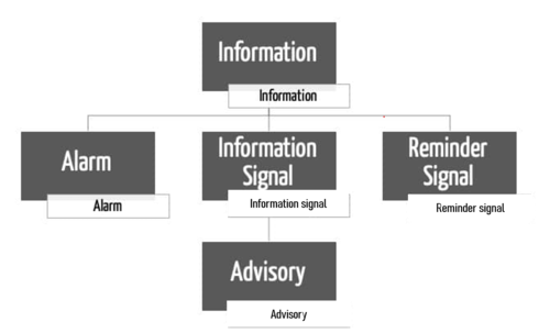
Definition: INFORMATION SIGNAL
“any signal that is not an ALARM SIGNAL or a REMINDER SIGNAL”
IEC 60601-1-8
Examples of information signals:
- Pitch in oxygen saturation
- ECG curve with the associated heart rate
- An advisory is a kind of information signal
- Indicator lights for the x-ray activity
- Warning and caution lights are also information signals
Information signals relate to the patient, the equipment or the workflow. They are not, however, indicators of possible damage and fundamentally do not require the operator to act, they merely require attention. An alarm condition, however, requires the operator to act and interrupt their work.
Amendment 2 introduces a special case within these information signals, advisories.
Definition: Advisory (AMD2, definition 3.38)
“An ADVISORY is a type of INFORMATION SIGNAL notifying the OPERATOR of a condition of the PATIENT or ME EQUIPMENT providing contextual awareness that is intended to improve the clinical workflow or understanding of the PATIENT condition, the awareness not being intended as a means of RISK CONTROL”
IEC 60601-1-8
Examples of advisories:
- A reminder that the next blood sample needs to be taken in around two hours
- The battery status display shows the remaining battery charge and advises the operator of a work step that needs to be carried out in the next few hours but for which it has not yet achieved an ALARM CONDITION for the status of the battery.
It is often difficult to differentiate alarms from advisories, and this is sometimes fluid. A rule of thumb may be able to help here:
Tip
Alarms are always needed when a specific action is necessary as otherwise damage may occur. Advisories, meanwhile, should explicitly suppress behavior that is being considered or has been started (e.g. opening a cover on equipment that is switched on).
Manufacturers often get creative with their choice of words so they do not have to meet the requirements of the standard. It is, however, the purpose that is critical rather than the term used. The standard also mentions this in the new amendment.
Finally, the IEC 60601-1-8 also defines a reminder signal:
Definition: REMINDER SIGNAL
“periodic signal that reminds the OPERATOR that the ALARM SYSTEM is in an ALARM SIGNAL inactivation state”
IEC 60601-1-8
c) Alarm vs. alert?!?
The English language differentiates between “alarm” and “alert”. It is particularly important to distinguish between the two.
Definition: Alert
“synonym for the combination of:
- PHYSIOLOGICAL ALARM CONDITIONS,
- TECHNICAL ALARM CONDITIONS and
- ADVISORIES”
IEC 60601-1-8 AMD2:3.41
The authors combine alarms and advisories in the term alert. The authors wish to make clear that the use of the term alert instead of alarm does not per se exclude the applicability of IEC 60601-1-8.
Tip
Systems which only provide advisories or information, however, are not in the scope of the IEC 60601-1-8.
The IEC 60601-1-8 merely requires alarms to be clearly differentiated to prevent confusion. Requirements of the presentation of advisories and information can be found in the basic standard IEC 60601-1 or in the individual standards IEC 60601-2-X.
d) Signals vs. indicator lights
The IEC 60601-1-8 uses the term Indicator Lights. However, it does not define the term.
Indicator lights are a visual addition to the acoustic alarms or can be used as an advisory of an intentional dangerous situation (not fault). Examples of this include:
- Active HF signal
- Active x-ray
- Hot surface which should not be touched (non-illuminated heating)
Indicator lights related to alarms are referred to in the IEC 60601-1:AMD2 as Alarm Indicator Lights. These indicator lights must always flash. Advisory indicator lights, meanwhile, must be constantly illuminated (see Table 2, IEC 60601-1:AMD2).
The IEC 60601-1:AMD2 counts advisory indicator lights as information signals (see Table 2 and blog article AMD2).
Indicator lights used as warning and caution advisories (see examples) are treated as safety marks. The requirements of the advisory indicator lights are can therefore be found in the basic standard IEC 60601-1 and some of the individual standards. The requirements of the alarm indicator lights (flash frequency) can be found in IEC 60601-1-8.
e) Summary and examples
A cardiopulmonary bypass machine is used as an example to assign the correct terms to the various types of information.
Type of information | Term, consequence, danger | Term |
Air in the system | Air can lead to an embolism | Technical alarm |
Advisory: Next replacement of the oxygenator in 4 h | Clinical management | Information (no alarm) |
Failure of the air bubble detector | Air bubbles not detected, embolism | Technical alarm |
Battery display showing remaining charge | Clinical management | Information |
Battery low | Equipment fails | Technical alarm |
Oxygen saturation display | Attention of the operator | Information |
Blood temperature display | Attention of the operator | Information |
Level falls below limit | Potential damage | Physiological alarm |
Failure of the alarm system | No monitoring | Technical alarm |
Power failure display | Equipment fails, no function | Technical alarm |
Area of the speed display marked in red |
| Information |
Display that the speed set is too high for a patient | If damage results from this: | Alarm |
Display that the speed set is too high for a patient | If no damage results from this: | Information |
Actual speed deviates from the TARGET set | Error cannot be identified can leads to damage | Technical alarm |
Heating and cooling unit in operation |
| Information (green indicator light) |
3. Requirements of the IEC 60601-1-8
a) Requirements of the product including generating the alarms
The standard sets out specific requirements of the alarms. These include:
- Volume
- Pitch
- Duration
- Repetitions
- Priorities
Amendment 2 even provides specific examples of undulations (see below).
b) Documentation requirements
The IEC 60601-1-8 sets out specific specifications for manufacturers for the documentation including accompanying documentation.
To be documented | Typical location |
List of the risks for which an alarm is the measure that should be used to manage the risk | Risk management files |
Technical description of the function (algorithms, design, statuses etc.) of the alarms | System Requirements Specification, system architecture |
The prioritization of the alarms (primarily by severity and speed of occurrence of damage) | System Requirements Specification |
Factors for the sensitivity of an alarm (sensitivity, specificity) | System Requirements Specification |
Disclosure of the algorithms and functionality of the alarm system | Instructions for use |
c) Testing requirements
The IEC 60601-1-8 also sets out specific specifications for the testers (e.g. a test laboratory). The tests must comprise:
- Completeness of the instructions for use
- Function of the alarm system
- Visibility of the alarm signal
- Audibility of the alarm signal (volume level, time-related features: tone sequences, frequencies, pauses, etc.)
- Correct functioning of the alarm behavior (alarm off, alarm suppression, etc.)
- Function under certain circumstances (EMC, operation, etc.)
- Risk management files (criteria for the alarm, malfunctions in the alarm system)
- Correct function and labeling of the operating elements
- Technical description of the alarm system
- Validation of the alarm system (usability files)
4. Amendment 2 (AMD2:2020)
a) Background
The IEC 60601-1-8 was most recently amended in [2012] by Amendment 1. It is also referred to as “version 2.1”. Since then there have been other proposed changes, 20 of which were classed by the European Commission as urgent. These were included in Amendment 2 in 2020, also known as “version 2.2”.
All of the remaining points (“long list”) are to be included in a third version which is planned for 2024 or later.
b) Overview of the most important changes
The scope of 62 pages alone is enough of an indication of how important and extensive the changes are. They include:
- Update to the dated references to referenced standards
- Text corrections
- New and amended definitions
- Addressing the risks linked to alarm flood or alarm fatigue
- Improved techniques for the perceptibility of acoustic alarms
- Differentiation of the terms alarm, advisory, warning, and information
- Corrected test to measure the sound pressure
- Distributed alarm systems (distributed information systems): section fully revised and inserted
- New graphical alarm symbols
The following sections address some of these points.
c) Alarm fatigue and alarm perceptibility (point 4)
Background and problem
Alarm signals improve the perceptibility of an alarm situation (dangerous situation) and therefore have a significant impact on the clinical management and the patient risk. Alarm signals are generally characterized by their presentation (acoustic, visual, acoustic + visual) in combination with the task requirement (priority).
The authors identified two problems linked to the alarms in various tests:
- Alarm fatigue
- Poor alarm perceptibility or distinguishability of acoustic signals
Alarm fatigue
Alarm fatigue is increased by
- excessive alarms,
- annoying, irritating alarms, or
- false positive alarms.
The standard wants to increase manufacturers’ awareness of the known problem of alarm fatigue and asks manufacturers to take the effect into account when designing the alarm user interface.
The standard generally views alarms as part of a risk activity. There would therefore be a positive risk/benefit ratio if an alarm system only indicated clinically relevant alarm situations that require an action within an appropriate amount of time. The standard calls these alarms “clinically actionable”.
The effectiveness of the risk activity should therefore not be reduced by too many or incorrect alarms. In this context, the standard introduces the following new terms:
- ALARM FATIGUE (3.39)
- ALARM FLOOD (3.40)
- NUISANCE ALARM SIGNAL (3.50)
- CLINICALLY NONACTIONABLE (3.45)
- CLINICALLY ACTIONABLE (3.44)
The standard does not set out specific requirements for technologies such as intelligent alarm systems or the accuracy and correctness of alarms. Manufacturers must rather take these aspects into account when designing the alarm system (performance specification) and in the risk analysis.
Alarm | Significance | Risk | Options |
False negative | No alarm when there is an alarm situation | Operator does not notice a patient’s critical condition or only notices too late. Can lead to frustration and decreased user acceptance. | Specifying limits between false negative and true negative |
False positive | Alarm when there is no alarm situation | Are not clinically relevant and are disruptive (NUISANCE ALARM SIGNAL) and lead to delayed, unnecessary, inappropriate, or no user actions and worsen attention (ALARM FATIGUE). In some cases, users may turn the alarm off. | Improved algorithms, delays in alarms |
True positive | Alarm when there is an alarm situation | Too many (disruptive) alarms (ALARM FLOOD) which do not require immediate action (CLINICALLY NONACTIONABLE) because the priority has been incorrectly assessed or the user is already aware of the situation can lead to inappropriate user actions or worsen attention (ALARM FATIGUE). | Improved algorithms, discussing the relevance of the alarms with users (considering the risks/benefits) |
True negative | No alarm when there is no alarm situation | None |
|
d) Poor alarm perceptibility of acoustic signals
(Point 5 of the list in section 4 b))
Acoustic signals are often not sufficiently effective because they are either
- difficult to differentiate and confusing or
- are difficult to link to a critical situation.
The acoustic alarm signals are the first and often only indicator for the perceptibility of an alarm situation. Accordingly, the acoustic alarm signals have a particular importance in the standard and must also meet the usability requirements as part of the user interface (auditive interface).
Relevant criteria for the usability of acoustic signals are:
- Learnability
- Localizability
- Audibility
- Perceptibility (self-descriptiveness)
- Individualizability
To date, the standard has set out melodic tone sequences for the coding of the information (perceptibility) in an alarm signal (see Annex F).
In various tests the authors determined that the melodic alarm signals (Annex F) only fulfil the above-mentioned criteria for usability to a certain extent and do not correspond to the latest technology (and science).
Scientific tests in other areas (avionics, engineering) show how effective, usable acoustic interfaces can be designed. This has led to the development of further techniques, e.g.:
- Auditory Icons
- Auditory Pointer
The basic idea is to create a link between an acoustic signal and a known reality, such as a coughing sound which indicates dangerous levels of carbon monoxide.
From an evolutionary perspective, our hearing is able to differentiate complex noises and cognitively process them.
The authors therefore introduced the Auditory Icons and Auditory Pointer in Amendment 2. These are briefly presented below.
Auditory Icons
“sound that creates a strong semantic link to the category it represents”
Auditory Icons have a much stronger link to the alarm condition than abstract sounds, are easier to localize and more resistant to masking. The selection of specific AUDITORY ICONS for specific functions means that confusion with noises which naturally occur in a clinic environment is avoided.
The authors are so convinced of the applicability of the Auditory Icons that they claim that a user who has not perceived the Auditory Icons would not have perceived the conventional alarm signals either.
Table G.4 shows a list of the Auditory Icons that have already been validated for the most common alarm conditions.
Table G.4 – Characteristics of the AUDITORY ICON
SOURCE of the ALARM CONDITION | AUDITORY ICON metaphor | AUDITORY ICON description | File name of AUDITORY ICON |
General | none | none | — |
Cardiovascular | “Lup-dup” ; heartbeat sound | A stylized, square/triangle wave-based “ heartbeat“ sound with no discernible frequency. Six PULSES formed from three 2- PULSE “lup-dup” sequences | |
Artificial perfusion | Liquid disturbance, water churning, bubbles | Two approximately 1 s sequences of a strong water bubbling sound, separated by silence | |
Ventilation | A single inhale followed by an exhale | A 1 s inhaling sound (like white noise), followed by a 0.5 s gap, followed by a slow exhale with a long tail | |
Oxygenation | Irregular, stylized dripping/saturation | Stylized irregular temporal pattern with some discernible pitch; a two-tone sequence superimposed on the six-tone pattern | |
Temperature/energy delivery | Whistling kettle | Complex sound including high frequency harmonics, rising slowly over approximately 2 s | |
Drug or fluid delivery/administration | Shaking pill bottle | Two 0.8 s sequences of a 4-rattle shaking sound | |
Equipment or supply failure | Starting up a motor that shuts down suddenly | Spectrally complex sound of a motor revving up (increasing in frequency) over approximately 1.2 s then an abrupt stop tailing off for approximately 0.5 s |
See for yourself whether you can correctly assign the alarms. The standard also provides the examples.
Auditory Pointer
“sound that attracts attention, denotes the priority and aids in localization of the COMMUNICATOR”
Auditory Pointers “point” to the source of the alarm (type of equipment and which patient) and indicate the priority and criticality (high, medium, low) of the alarm status. An auditory pointer shows spatial parameters as acoustic parameters.
Tables G.1 and G.2 show the spectral, amplitude and time variables for the HIGH PRIORITY, MEDIUM PRIORITY and LOW PRIORITY.
The standard then sets out tone parameters which can be used to model the urgency, audibility, and localizability.
- Urgency: Pitch, volume, frequency of repetitions, harmony
- Audibility: Frequency range, amplitude, harmonics
- Localizability: Complexity of the sound
Here, too, the ISO provides examples.
e) Validation of the alarms
(see 4 c) and 4 d))
The standard suggestions from tables G.1 to G.5 have already been clinically validated by the authors and do not need to be checked again. This also relates to the alarm signals that remain valid according to tables 3 and 4.
The authors tested the Auditory Icons (Annex G) against the melodic alarm signals (Annex F) with user groups in a clinical environment. The Auditory Icons were clearly superior.
This article shows an example of a possible test setup for a formative or summative usability assessment.
If, however, you develop your own alarm signals, Auditory Icons and Pointers, you must validate the effectiveness in a real or simulated clinical environment using the following criteria.
- Speed of identification
- Accuracy of identification
- Localizability
- Task requirement (priority low, high)
- Learnability
In Annex H, the standard also provides a test framework for the summative assessment and acceptance criteria for the aspects of learnability, localizability, and perceptibility.
5. What you can do now
a) 12 steps to check conformity
Manufacturers who have been manufacturing and distributing their systems for a long time and have not reviewed against the latest technology since 2012 (last amendment to the IEC 60601-1-8) should check their system for conformity and create a PMS report. The following 12 steps are helpful:
- Lists of all displays and advisories (including warning symbols)
- In the risk analysis, check which displays and advisories are defined as risk measures and must be considered to be risk measures in the sense of the standard
- On the basis of section 2 which classifies displays as
- Alarm signal (patient, technical), or
- Information signal (includes advisories), or
- Indicator lights
- Determine which displays cannot be clearly defined or are incorrectly assigned.
- Clearly define the purpose and function of these displays depending on section 4
- In the case of the alarms, check whether the priority of the alarms is appropriate for the necessary urgency and reaction time and comply with the ranking (high, middle, low).
- Create a test plan and test specifications for the usability of alarm signals you have developed yourself (see the criteria in IEC 60601-1-8: AMD2, Annex H)
- Check whether the requirements of the visual representation of all displays according to IEC 60601-1:AMD2 (Table 2) are met
- Document the GAP analysis and implementation plan
- Check whether the architecture is suitable to technically separate the alarm source and the display (communicator) You can then replace the alarm sets with one another.
- Repeat the check of the alarm-related requirements of the IEC 60601-1 and IEC 60601-1-8 in a laboratory
- Supplement the PMS plan with feedback on the alarms or where appropriate define log data (alarm logging is already requested by the standard)
b) Timeline for implementation
Europe
In the EU, Amendment 2 is on the list of standards which will be revised and harmonized by May 2024 (see standardisation request-MDR-IVDR).
According to AMD 2, section 6.3.3.1 d) the melodic alarms previously recommended can continue to be used. It is, however, the authors’ intention to make the new ALARM SIGNALS from Annex G compulsory in the next amendment or edition of the IEC 60601-1-8.
The latest deadline for harmonization (EN 60601-1-8:2007+AC:2010+A11:2017+prA2) is planned for May 27, 2024. Version 3.0 of the standard, which plans to make the new alarm signals compulsory, is planned for 2024.
Whether and by when version 3.0 of the standard will be harmonized remains to be seen, but it is not expected to be within the next three years.
Rest of world
Market | Current status | Transition period | Comment |
FDA | IEC 60601-1-8 Edition 2.1 2012 | December 17, 2023 | FDA recognition of IEC 60601-1-8 Edition 2.1 2012-11 [Rec# 5-76] will be superseded by recognition of IEC 60601-1-8 Edition 2.2 2020-07 CONSOLIDATED VERSION [Rec# 5-131]. FDA will accept declarations of conformity, in support of premarket submissions, to [Rec # 5-76] until December 17, 2023. After this transition period, declarations of conformity to [Rec # 5-76] will not be accepted. |
Anvisa | ABNT NBR IEC 60601-1-8:2014 | No information | No information |
China NMPA | YY 0709-2009 (IEC 60601-1-8:2003) | No information | No information |
Canada CSA | CAN/CSA C22.2 NO. 60601-1-8:08 + AMD1:2012 | No information | No information |
Japan JIS | JIS T 60601-1-8:2012 | No information | No information |
6. Conclusion
Note the order of the risk-minimizing actions
The first impulse of many manufacturers is to manage risks through alarms and advisories. The MDR and IVDR set out the order in which actions of this type are to be determined. The inherently safe design is the first priority.
However, if there is no other choice than to manage the risks with alarms and other “signals”, these actions must be effective. A standard such as the IEC 60601-1-8 is therefore helpful because it provides specific specifications about how these alarms and signals should be designed.
Take into account the latest technology
These specifications are not constants, they must correspond to the latest technology. The fact that the authors of IEC 60601-1-8 are following the latest technology with the second amendment should therefore be welcomed. They are contributing to the safety of medical devices.
Although the scope of the IEC 60601-1-8 is limited to medical devices such as ME equipment, the specifications of this standard can also be helpful with other medical devices.
Act now
Manufacturers should immediately set out to check their conformity with the second amendment. The implementation of the twelve points set out above is helpful for this.
The Johner Institute helps manufacturers to develop safe, high-performance, and effective medical devices which meet the requirements of IEC 60601-1-8:AMD2. Get in touch (e.g. using the contact form) to find out how you can check the conformity of your products quickly and easily, restore this if necessary and document your analysis. Your auditor will value your efforts too.

Author:
Mario Klessascheck

Back To Top
Privacy settings
We use cookies on our website. Some of them are essential, while others help us improve this website and your experience.